FusionCharts Suite XT allows you to customize a drag-node chart in run-time - you can add, edit, or delete nodes in a drag-node chart. To avail this feature you need to render the chart in edit mode (edit mode can be enabled by setting "viewMode": "0" in the chart object).
In this section, you will be shown how you can:
Add a node at run-time
Edit a node at run-time
Delete a node at run-time
To understand this, the sample chart that we will use looks like this:
The above chart shows the US Subway Map and uses drag-able nodes to mark locations on the map.
The data structure needed to render the above chart is given below:
Adding a Node at Run-time
To the above subway map chart, we will now add a new node.
To add a node to:
From the bottom-left corner of the chart, click the
 button. A menu is rendered.
From the menu, select the
Add a nodeoption.

The node properties dialog box, as seen in the image below, is shown:
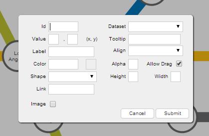
In this dialog box, enter the node information.
Click
Submit.
Given below is a brief description of the fields in this dialog box:
| Field | Description |
|---|---|
| Id | It is used to specify an unique identifier for the node. |
| Dataset | It is used to specify the data set to which the node will belong. The node inherits all visual properties defined for the data set. |
| Label | It is used to specify the label for the node. The label will be displayed on the chart. |
| Value | It is used to specify the x- and y-coordinates for the node position. |
| Tooltip | It is used to specify the tool-tip text for the node. |
| Color | It is used to specify the hex code of the color that will be applied to the node. |
| Alpha | It is used to specify the transparency for the node. This field takes values between 0 (transparent) and 100 (opaque). |
| Align | It is used to specify the vertical alignment of the label with respect to the node. This field takes the following values: top, middle, and bottom. |
| Allow Drag | It is used to specify whether the node will be drag-able. Selecting this check-box will make the node drag-able (default), clearing it will not. |
| Shape | It is used to specify the shape of the node. This field takes the following values: rectangle (default), circle, and polygon. |
| Height | It is used to specify the height of the shape.
This field is visible only when you have selected Rectangle from the Shape drop-down. |
| Width | It is used to specify the width of the shape.
This field is visible only when you have selected Rectangle from the Shape drop-down. |
| Radius | It is used to specify the radius of the shape.
This field is visible only when you have selected Circle or Polygon from the Shape drop-down. |
| Sides | It is used to specify the number of sides for the shape.
This field is visible only when you have selected Polygon from the Shape drop-down. |
| Link | It is used to specify the URL to which the user will be redirected to if the node is clicked. |
| Image | It is used to specify whether an image will be rendered with the node. Selecting this check box will make visible the fields that allow you to enter image information, clearing it will not render an image. |
| URL | It is used to specify the URL to which the user will be redirected to, if the image is clicked.
This field will be visible only if the Image check box is selected. |
| Width | It is used to specify the width of the image.
This field will be visible only if the Image check box is selected. |
| Height | It is used to specify the height of the image.
This field will be visible only if the Image check box is selected. |
| Align | It is used to specify the alignment of the image with respect to the node. This attribute takes the following values: top, middle, and bottom.
This field will be visible only if the Image check box is selected. |
The image below shows the fields of the dialog box populated for a new node:
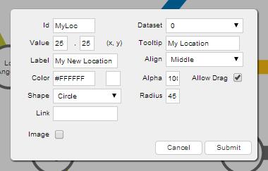
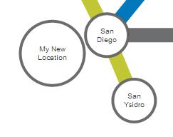
Now, when the Submit button is clicked, the new node created looks like this:
You can define nodes in the chart data using the data object of the dataset object.
Event Raised
When a new node is created, a Javascript event, named nodeAdded, is raised. You can trap and use this event to customize the output according to your requirements.
The code snippet required to trap this event is given below:
chartInstance.addEventListener('nodeadded', function(e, a){
    //Your code here
});
Editing a Node at Run-time
For a node, you can edit all its properties except for the ID and the dataset to which it belongs.
To edit a node:
Press and hold the left mouse button on that node. The node properties dialog box is rendered with the
IdandDatasetfields disabled.In this dialog box, re-populate the fields you want to edit.
Click
Submit.
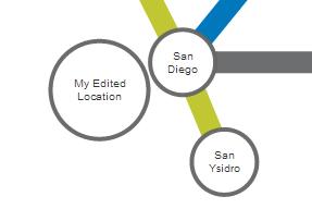
The image below shows the fields of the dialog box re-populated for the node we created above:
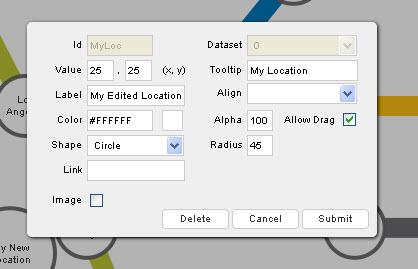
Now, when the Submit button is clicked, the edited node looks like this:
Event Raised
When a node is edited, a Javascript event, named nodeUpdated, is raised. You can trap and use this event to customize the output according to your requirements.
The code snippet required to trap this event is given below:
chartInstance.addEventListener('nodeupdated', function(e, a){
    //Your code here
});
Deleting a Node at Run-Time
To delete a node:
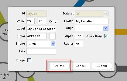
Press and hold the left mouse button on the node that you want to delete. The node properties dialog box appears.
From the dialog box, click
Delete. The node is deleted.
Event Raised
When a node is deleted, a Javascript event, named nodeDeleted, is raised. You can trap and use this event to customize the output according to your requirements.
The code snippet required to trap this event is given below:
chartInstance.addEventListener('nodedeleted', function(e, a){
    //Your code here
});
You can get the latest updated node positions using JavaScript or by submitting the updated positions to a server-side script.
There! You have now seen how you can add, edit, and delete nodes at run-time.
